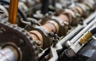
Continental and Lycoming typically rate their engine life from 1,600 to 2,000 hours of operation between overhauls on most models. However, the only owners likely to achieve that kind of rated performance are those who use their aircraft on a nearly daily basis. Why? The reason is not the flying. It’s the parking!
A primary culprit for premature aircraft engine overhaul is corrosion caused by condensation that occurs after shutdown. Aircraft engines that are used daily frequently reach their rated TBO because liquid condensate is boiled off on a regular basis. Low use rate often results in reduced engine life.
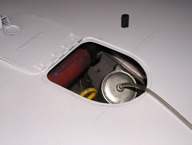
Air Inlet Fitting In Oil Filler Cap
As the engine cools and the internal temperature drops below the dew point, liquid moisture condenses out of the vapor and clings to internal engine surfaces. This liquid water then resumes its ongoing process of eating up your engine from the inside out. However, if the dew point can be made sufficiently low, then liquid water will never form. This engine dehumidifier provides a continuous positive pressure injection of extremely dry air (dew point approximately -100oF) on a 24/7 continuous flow basis. It is recovered at the crankcase blow-by vent, returned to the pump, dried again and re-injected in the oil fill port of the engine.
How it works
The dehumidifier is connected the engine as soon after engine shutdown as possible, before the engine cools. It is then run on a 24/7 basis. A small aquarium-type air pump forces ambient humid air though plastic bottle containing silica gel (this is the stuff used in shipping and storing aircraft engines and electronics).
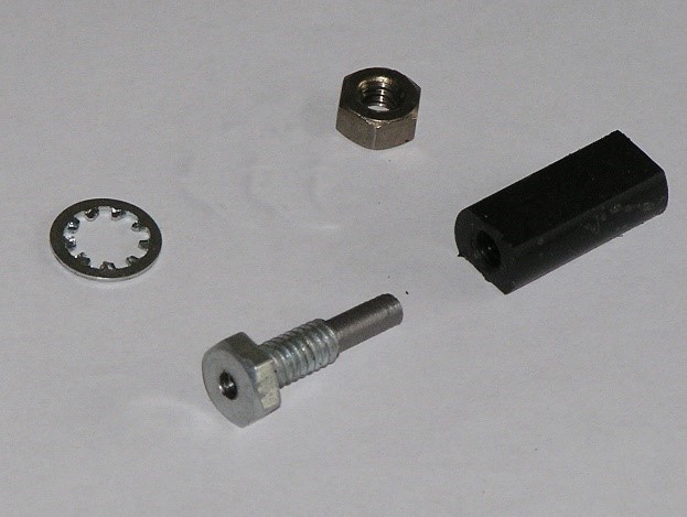
Air Fitting For Oil Cap
The silica gel has a great affinity for moisture and literally sucks it out of the air. The dried air is filtered and injected into the engine crankcase. Any moisture inside the engine vaporizes with the incoming dry air and is moved by the constant positive pressure from the air pump to the crankcase blow-by vent, then back to the pump and the silica gel dryer. At some point in time, the silica gel will absorb all the moisture it can hold. This is obvious because about 5% of silica gel crystals are dyed blue that changes to a pinkish color when saturated with moisture. At that point:
- Remove the saturated silica gel from the bottle
- Spread it out on a cookie sheet
- Heat in oven at 275o F until the silica turns blue again
- Cool and return to the bottle
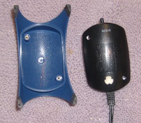
Disassembled air pump. Remove the felt
filter in the bottom of the pump and plug
the hole with glue.
The frequency of this recycle rate will depend up the humidity of the environment. This may vary from months or more in dry regions down to just a week or so in the humid southeastern United States. Adding more silica gel to the bottle will extend the service interval.
Build your own
Connect the drier output via Tygon plastic tubing to the engine oil filler cap. A return line of Tygon tubing is fitted to the crankcase blow-by port. The preferred means of connection is to drill a ¼” hole in the oil filler cap and then install a short standpipe to the cap. I modified the oil filler cap by installing a hollow ¼”-20 carriage bolt. (I used a lathe to cut off the threads on the leading ½” of the bolt. This permits a slip fit of the Tygon dry air supply hose.)
The hollow bolt was then installed on the oil fill cap. Additionally, I made a ¼”-20 threaded Delrin plastic plug to cap this little standpipe during flight. Also, you will need to make an adapter to fit the crankcase blow-by tube. This can be a rubber stopper drilled to fit the Tygon return hose or a piece of rubber tubing with the return Tygon tube hot glued into it. 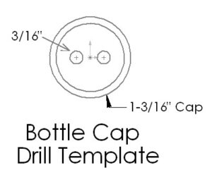
Please note that you will have to also devise a plug for the freeze-emergency blow-by vent located few inches up the blow-by vent pipe inside the aircraft engine nacelle. This can be a rubber flapper that normally closes the freeze vent. If the blow-by tube is frozen shut, crankcase pressure will push the rubber flap open.
The dehumidifier components consist of:
- A vibrating reed “silent” type aquarium air pump
- Two-liter plastic pop bottle with screw on cap
- Airstone aquarium air bubbler
- Ten feet of 1/8″ bore Tygon plastic aquarium tubing
- Twelve inches of 3/16″ outside diameter (1/8″ inside diameter) rigid plastic tubing
- One pound of 5% blue dyed silica gel
- ¼-20 custom air fitting hollow bolt
- Pump air intake tube
Note: Low-cost aquarium pumps do have an irritating 60 Hz buzz caused by their vibrating reed design. So-called “silent” pumps are the same design but are supported in a manner that will minimize noise. If you spend a lot of time in the hangar, I strongly recommend the “silent” type pump.
To construct the dehumidifier, you will need an X-acto knife, a drill and ¼” and 3/16” drill bits, a hot glue gun, and gel super glue.
Extending the dessicant recycle time
The following modification can extend the intervals between service times for the desiccant. It revamps the dryer cycle from an open- loop system into a closed-loop. Dry air is still injected as before into the oil filler neck, but in addition, a vacuum line is attached to the crankcase blow-by tube that returns dry air back through the engine. This eliminates the continuous drying of external incoming humid air into the system and provides for continuous circulation of ever-drier air in the crankcase.
Implementation
The air pump must be converted to a blow-and-suck configuration. To do this you will need to make an additional fitting for the air intake port next to the air output port on the pump. Drill a 3/16” hole about ½” to the right of the exhaust port. Remove the felt filter in the belly of the pump case and plug the hole with glue.
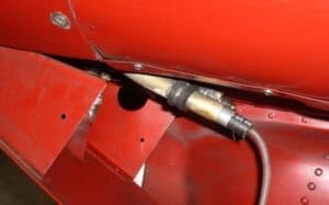
Pump Return Line Installed In Blow By Port
To work as a vacuum pump, the pump case must be made airtight. This is done by disassembling the air pump case (two screws) and applying RTV silicon aquarium cement around the entire case seam and around all four sides of the power cord strain relief. Then reassemble the case and allow it to dry. Also, add RTV glue to any screw heads or tape over recess holes in the case bottom for an airtight seal.
You will also need to make an adapter fitting such as a rubber hose or rubber stopper fitted with a length of the Tygon tubing to serve as an air return to the pump.
Fabrication
Drill two 3/16” holes about ¼”off the center in the top of the bottle cap, close enough to the center to allow easy tube clearance of the bottle neck interior wall. For the pump inlet input, insert a 2” length of the rigid tubing in one hole and hot glue it into place. Insert the remaining 10” rigid tube in the other hole and hot glue it so the bottom end of the tube is positioned about 2″ from the bottom of the bottle.
Use a 1″ length of the Tygon flex tube to connect the aquarium bubbler airstone to the end of the longer rigid tubing. The Airstone is used as a dust filter to keep silica gel particles out of the engine. The airstone should lie on the bottom of the bottle.
To prep the silica gel, it in your kitchen oven at 275oF until the dyed silica gel pellets turn blue (they are pinkish when saturated with moisture). Open the bag and pour the contents into a clean and dry two-liter pop bottle. Insert the airstone/tube assembly, work the airstone to the bottom of the silica gel, and tighten the cap. Do not delay, as it will absorb moisture from the air.
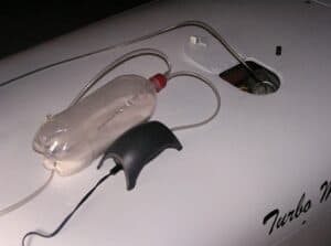
Open-loop dryer assembly
Use about a foot of the Tygon tubing to plumb the air pump to the short air input stub. Connect 6 feet or more of Tygon tubing to the airstone-equipped exit port, then to the air fitting on the oil filler cap. Connect the pump return line to the crankcase breather port via an airtight rubber seal.
Note: All connections and seals must be a leak-tight fit. Mating via the crankcase blow-by vent tube (usually located near the firewall) may be done by inserting a piece of the rigid tubing through a 3/4” closed-cell-foam ball or a tightly fitting rubber stopper.
A secondary modification required is a plug for the freeze slot in the blow by tube. This can be a rubber flap around the blow-by pipe that is normally closed over the freeze slot, but is pushed open by crankcase pressure if the exit end of blow-by tube end should freeze shut. Finally, a foam plug fitted to your aircraft’s air intake with a “REMOVE BEFORE FLIGHT” flag attached will close up the system circulation (in the case of a crankshaft position that leaves an intake valve open).

